
How to Use the Praxiline Structural Drafting Set
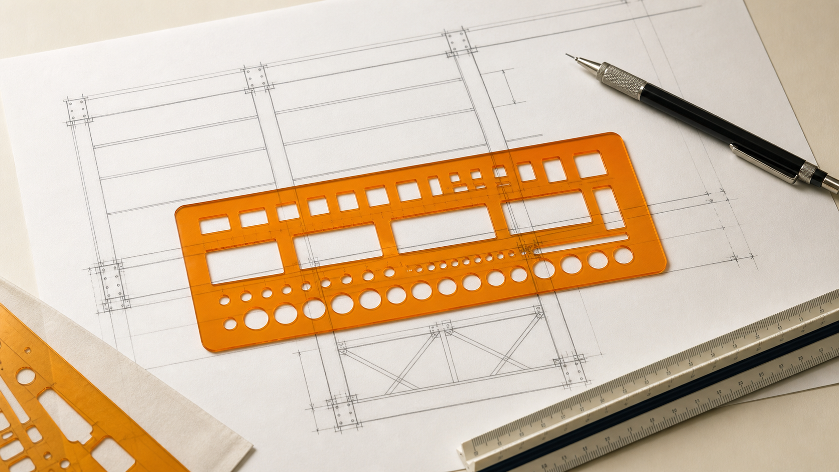
The Praxiline Structural Drafting Set helps you create clean, repeatable representations of common structural shapes and linework by hand.
One set includes six reusable stencil pieces: one W-shape stencil, one channel stencil, one angle stencil, one structural linework and detail stencil, and two dashed-line guides.
This guide explains how to select the appropriate stencil, interpret its markings, position it on the drawing, and complete a clear structural sketch.
1. Understand how the shapes are represented
The openings produce structural shapes that remain clear and recognizable when drawn by hand. Certain dimensions are intentionally represented graphically rather than at their exact scaled thickness.
- Flange, web, and angle-leg thicknesses are not drawn to scale.
- These elements have enough visible thickness to avoid appearing as zero-thickness lines and to remain legible on paper.
- The channel stencil provides multiple nominal depth references but uses one representative flange width.
- Do not measure traced outlines to determine actual member dimensions or section properties.
These intentional simplifications improve readability. The complete written member designation—not the proportions of the traced outline—defines the actual structural section.
2. Identify what you need to draw
Begin by identifying the structural element or linework required in your detail:
- W-shape: Use the W-shape stencil for wide-flange beams and columns.
- Channel: Use the channel stencil for C-shape members.
- Angle: Use the angle stencil for L-shape members.
- Structural linework: Use the detail stencil for common line types, breaks, corners, and other drawing elements.
- Dashed line: Use the dashed straightedge for hidden, overhead, or reference lines where appropriate.
Choose the stencil based on the element being represented, not simply the opening that best fits the available space.
Short video demonstrations
See each stencil in action
Choose a tool below to see how it is positioned and traced. Each demonstration uses simple playback controls so you can pause or replay a step while you work.
3. Confirm the stencil scale
Before tracing, check the scale printed on the selected stencil. The set includes features designed for:
- 1½″ = 1′-0″
- 3″ = 1′-0″
Use the scale that matches your detail whenever possible. Do not assume every piece uses the same scale; check the marking whenever you change stencils. If the sketch is intentionally not drawn at a measurable scale, mark it NTS.
Working with other scales
The printed scales can serve as proportional references for certain conceptual sketches. A shape may be represented approximately at half or twice the printed scale by selecting dimensions that compensate for the difference.
- To use a 3″ = 1′-0″ feature on a drawing at 1½″ = 1′-0″, select a stencil dimension approximately one-half of the intended dimension.
- To use a 1½″ = 1′-0″ feature on a drawing at 3″ = 1′-0″, select a stencil dimension approximately twice the intended dimension.
For example, an 8-inch reference used at twice its printed scale could proportionally represent a 16-inch dimension at the final drawing scale.
This method remains an approximation. Actual rolled sections do not necessarily scale proportionally, and the available depth, flange-width, and leg-size combinations may not correspond to a manufactured section.
If you use a proportional conversion:
- Confirm the conversion before drawing.
- Clearly state the actual drawing scale.
- Write the complete intended member designation.
- Do not derive dimensions from the finished outline.
When accurate scaled geometry is required, verify and draw it using the actual section dimensions.
4. Select the member size or reference
Use the printed numbers and arrows to locate the opening or reference marks associated with the member you want to represent.
W-shapes
Use the labeled depth and flange-width references to establish the desired wide-flange representation. The visible flange and web thicknesses are graphic drafting widths; they do not represent the actual scaled thicknesses of a specific W-shape. After tracing, label the member with its complete designation, such as W12×26.
Channels
Use the channel labels to select the intended nominal depth, such as C4, C6, or C8. Because the stencil uses one representative flange width for the available depths, the traced flange width and thickness do not reproduce the exact proportions of every rolled channel. Add the complete designation, such as C8×11.5, when known.
Angles
Select the required nominal leg-size reference using the numbered angle openings. The visible leg thickness is enlarged for clarity and does not represent the actual scaled material thickness. Add the complete designation, including the actual leg dimensions and thickness, such as L4×4×3/8.
The printed references help create recognizable, consistent shapes. They do not replace complete member designations, verified dimensions, published section properties, or applicable design documents.
5. Establish the member location
Lightly mark the member centerline, grid intersection, elevation, or other controlling reference before positioning the stencil. Align the stencil with that reference and hold it flat with enough pressure to prevent movement, without shifting the paper or stencil.
For repeated members, establish light construction lines first. A common baseline or centerline helps keep traced shapes consistently aligned.
6. Position the stencil
Place the selected opening over the intended member location and check its alignment against the centerline, grid line, reference edge, or previously drawn geometry.
Before tracing, confirm that:
- You selected the correct stencil.
- You identified the applicable scale or proportional conversion.
- The shape faces the intended direction.
- The member is centered or aligned correctly.
- Enough space remains for dimensions, labels, and connection information.
For mirrored or reversed conditions, rotate or flip the stencil while maintaining the same controlling reference.
7. Trace the shape
Place a pencil or technical pen against the selected edge and trace using steady pressure. Keep the instrument at a consistent angle so the line remains uniform.
When a shape requires several connected strokes:
- Trace one edge at a time.
- Keep the stencil stationary between strokes.
- Complete short corners carefully.
- Remove the stencil before extending or darkening the lines.
A fine-point pencil or pen generally produces the clearest result. Tip diameter, line weight, and tracing angle can slightly affect the finished outline—another reason not to measure dimensions from a traced shape.
If necessary, use a straightedge after removing the stencil to extend framing lines or connect the shape to the surrounding detail.
8. Add structural linework
Use the linework stencil to add the symbols or line configurations required to complete the detail. The dashed straightedges may be used for hidden edges, overhead elements, elements beyond the viewing plane, or other line types consistent with the applicable drawing standards.
Choose line types according to the meaning they carry. Avoid using dashed lines solely for visual separation if they could be interpreted as hidden or overhead geometry. When repeating a pattern, align the stencil with a common reference to maintain consistent spacing and orientation.
9. Apply a clear line hierarchy
Once the main geometry is established, use line weight to distinguish different kinds of information:
- Use firm, darker lines for primary structural elements.
- Use lighter lines for grids, centerlines, and construction references.
- Use consistent dashed lines for hidden or overhead geometry.
- Use the lightest practical lines for temporary layout marks.
The appropriate hierarchy may vary with your office standards, drawing medium, and intended reproduction size.
10. Label and dimension the detail
After completing the geometry, add the information needed to communicate the structural intent:
- Complete member designation
- Dimensions and offsets
- Elevations
- Grid references
- Material and connection notes
- Section and detail references
- Applicable drawing scale or NTS
Keep labels outside the primary geometry where practical. Use short, clear leaders and ensure each note points unambiguously to the intended element.
Because flange, web, and leg thicknesses are represented graphically, the written designation is essential. Do not expect a reviewer to determine member size or thickness by measuring the traced outline. If you used a proportional scale conversion, clearly label both the actual member and intended drawing scale.
11. Review the completed sketch
Before finishing, confirm that:
- The appropriate stencil was used.
- The drawing scale or NTS designation is shown.
- Any proportional conversion was applied correctly.
- The complete member designation is written clearly.
- The outline is not being used to communicate an exact flange, web, or leg thickness.
- Repeated elements are aligned consistently.
- Dimensions and leaders point to the correct locations.
- Solid, dashed, and reference lines have distinct meanings.
- The primary structural idea can be understood without additional verbal explanation.
If the graphic representation could be mistaken for exact geometry, add dimensions or notes to clarify the design intent.
Recommended workflow
Identify the element confirm the scale select the size or reference establish the location position the stencil trace the geometry add linework label and dimension review the sketch.
Following a consistent sequence makes structural sketches faster to produce, easier to revise, and clearer for others to review.